Smart Fusion
Providing accurate loacalization and orientation estimations using UWB and IMU sensor fusion, allowing for more intuitive smart home device management.
Final Report
Table of Contents
- Abstract
- Introduction
- Related Work
- Technical Approach
- Evaluation and Results
- Discussion and Conclusions
- References
Abstract
As the number of smart devices in a household continues to grow, there is need for a system to be able to distinguish between and control the devices. The goal of this project is to develop a system building off of sensors available in current smartphones to allow a user to easily manage and interact with multiple smart devices indoors. Current smartphones are equipped with both IMU and UWB sensors. By fusing these sensors measurements and introducing two UWB anchors, we can sucessfully provide orientation and pose estimations of a users controller or phone. With known positions of the devices in a room, we can then deduct which device a user is pointing at to be controlled in a room and render it in a custom GUI. After this selection is made the user can control the smart device with stimulus broadcasted over BLE.
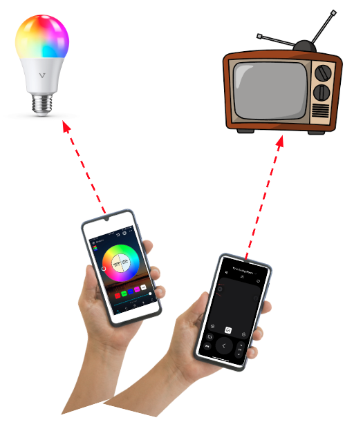
Figure 1: Smartphone controlling smart devices
1. Introduction
Motivation & Objective
Current estimates expect the number of IoT devices to hit 30 Billion by 2025 assuming continous exponential growth [1]. Considering the rapid growth of avaiable devices, the number of smart devices that each individual user is likely to manage also continues to grow. This increase in devices per user makes it continuously harder for users to manage and control their devices in an intuitive way. The goal of the project is to create a localization and orientation technique for detecting and controlling smart device objects in a room via pointer control using only the sensors available in current smartphones. The project aims to accomplish this with the least amount of additional sensors possible.
Todays Limitations
The most common localization techniques in use today include GPS, bluetooth, or Wi-fi ranging. The localizations techniques have accuracies in the range of 1-5m and so are generally not considered to be precise enough to distinguish interactions in a typical home setting. Additionally these techniques each have ranging capabilities which also can have limitations. An example of the limitations include not being able to detect users position inside buildings with cement walls in the case of GPS or needing to be within very close proximity for BLE and Wifi and relying on signal gain measurments. UWB ranging techniques on the other hand offer localization accuracies within +/-20cm per anchor tag pair and can work indoors. This position tracking precision is required for users to be able to control devices indoors and be able to distinguish between multiple objects in a room.
Novelty, Rationale, and Impact:
This project is novel because it presents a feasable method for intuitively managing smart devices, and provides a novel approach to localization techniques using UWB and IMU data. These localization and orientation techniques also can be used for many applications beyond the intended use case, such as automatic device powering depending on a user positions in a home, tracking a users movements during the day, and locking and unlocking secure devices depending on the user and their position/movements.
Challenges:
- Use as few UWB anchors as possible while still providing accurate location data.
- Succesfully process IMU data to understand directional movements and position of humans while being able to filter out IMU drift.
- Accurately fuse orientation and position to make predictions about intended line of sight object selections.
Requirements for Success:
- Create a “Smart Controller” with a IMU and UWB sensor connected to ESP32 microcontroller to be used to test estimation accuracies.
- Tune UWB responders and initiator antennas to offer accurate position measurements.
- Filter UWB position estimates to allow for continous, non-noisy readings.
- Create a GUI which illustrates positions of objects in a room and the guesses which object the controller is pointing to/interacting with.
- Demonstrate the use of a controller on a smart object with multiple smart object in a room.
Metrics of Success:
- Positional Accuracy (x, y, z)
- Orientation Accuracy (Alpha, Beta, Gamma)
- Cost and number of sensors needed to perform localization
- Ability of controller to distinguish between multiple objects in a room
2. Related Work
Indoor localiztion is a wide area of research that this project builds upon. Two specific techniques for indoor localization that are used in this project are UWB indoor localiztion and IMU localization. Background on curtrent state of the art techniques are shown in the following paper reviews to provide background for the techniques used by this project.
UWB Indoor Localization In a paper by Zwirello et al. [2] indoor localization using UWB is done by rigging a space with many anchors which range to a tag somewhere in the space. This group analyzed both the optimal locations for placing UWB anchors in a space as well as the optimal algorithms for converting the ranging data into an absolute position. The following figure shows an example scheme of anchors in a cube space.
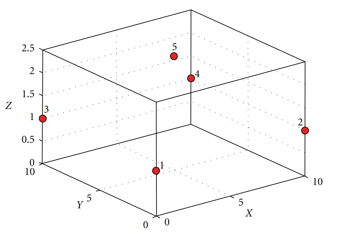
Figure 2: Example UWB anchor scheme [2]
In order to find an optimal positioning algorithm, this group did not limit the number of available anchors for a given tag. For systems using few UWB anchors they found that the optimal approach is to simple estimate the location of the tag as somewhere on the surface of a sphere centered at each anchor with a radius equal to the range measurment. For a 3-D space, 4 anchors are need to pinpoint the location of a tag to one point. As this project uses a maximum of 2 anchors, the best estimate is somewhere on a circle that is the intersection of 2 spheres. A representation of this intersection is shown in Figure 3.
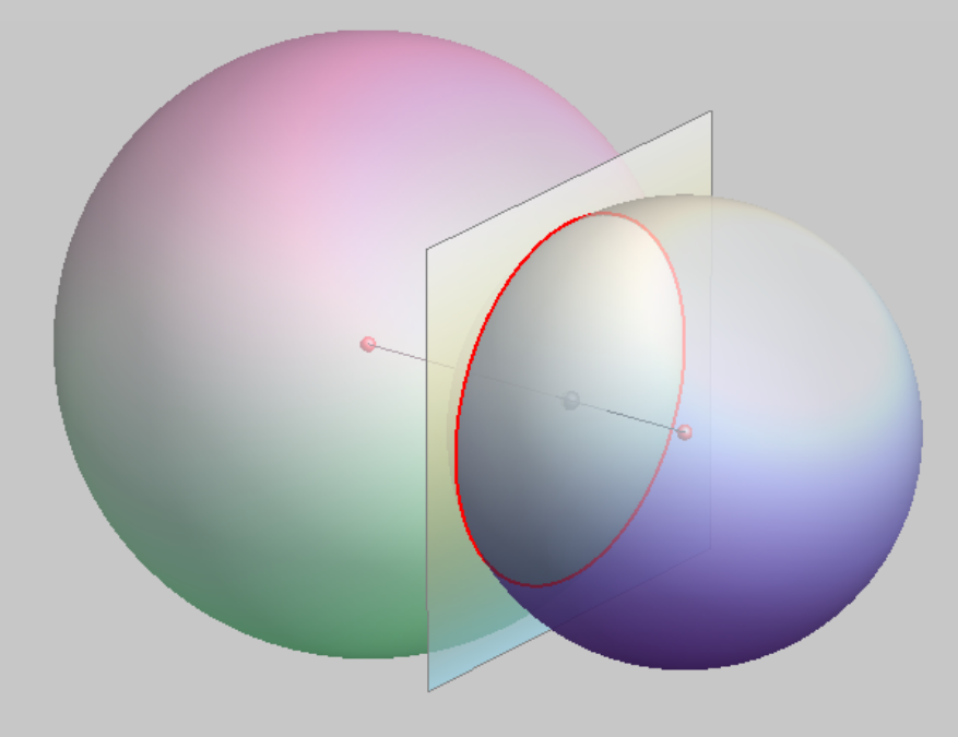
Figure 3: Intersection of two spheres [2]
IMU Indoor Localization In a paper by Ibrahim et al. [3] indoor localization was achieved using a 9-DOF IMU sensor and a barometric pressure sensor. The basis of the system was to find the derivative of the acceleration to obtain the jerk and then take the triple integration of jerk to determine displacement. This is done in an attempt to reduce the effects of sensor drift on the overall measurements. The pressure measurement was used to estimate the height by making assumptions about how atmospheric pressure decreases as height increases. They then passed these measurements through a Kalman filter to find the displacement estimates and were able to track a walk through a multi-story building within 3% error. The graph of this experiment is shown in Figure 4.
![IMU Localization Experimetnt [3]](./media/IMU_experiment.png)
Figure 4: Graph of IMU localization experiment [3]
This data is very impressive and lends some support to the feasibility of doing human localiztion with IMU data, but they relied on several crucial assumptions. The assumptions made by this group was that the subject have the IMU sensor attached at the belt and that the subject would always be moving forward. For this project, the user must be allowed to wave their smartphone around the room to point at smart devices, and so the assumption of having the IMU be fixed on the body was simply not feasible. Allowing the user to wave the smartphone around introduces far too much noise in the readings to extract any useful data to predict position from the IMU data.
3. Technical Approach
Hardware
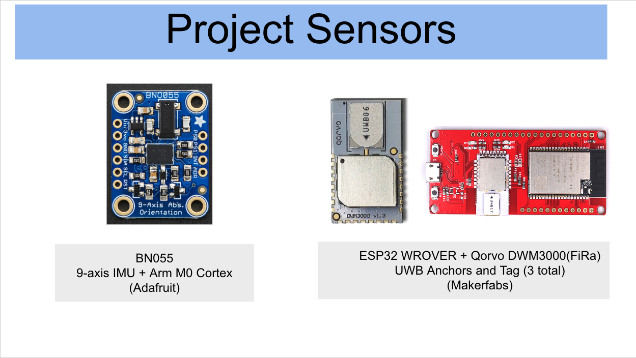
Figure 5: Sensor Hardware
- BN055 9-axis IMU
- ESP32 Wrover
- Qorvo DWM300 (1 Initiator, 1 Tag)
This hardware was assembled on a breadboard which had a push button and green LED to represent a controller or smartphone. This button would be replaced by a phone and interactable touch screen controls in the future. The button was used to calibrate the controller to indicate how it was aligned with the room, and to interacte/toggle the smart lights that were used during testing. It is importnant to note the the DWM300 is FiRa compliant and thus can be programmed to interact with devices such as iphone 11+ and other smart phones.
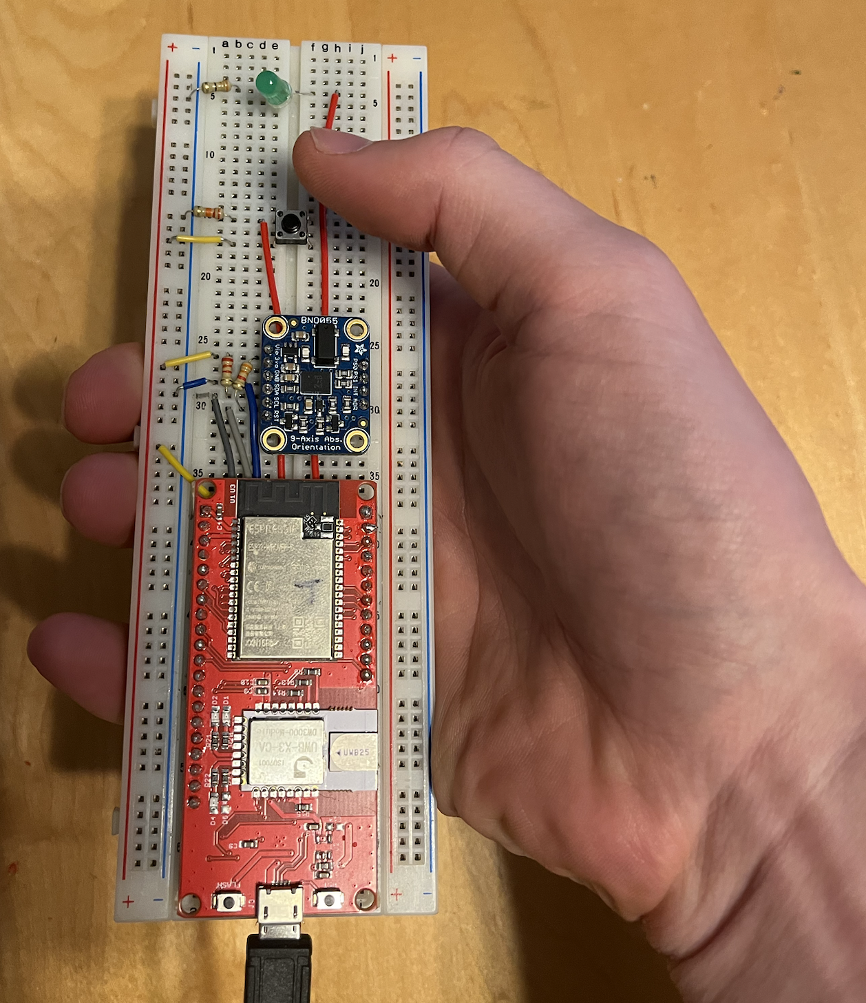
Figure 6: UWB + IMU "Smart Controller"
Sensor Fusion Approach
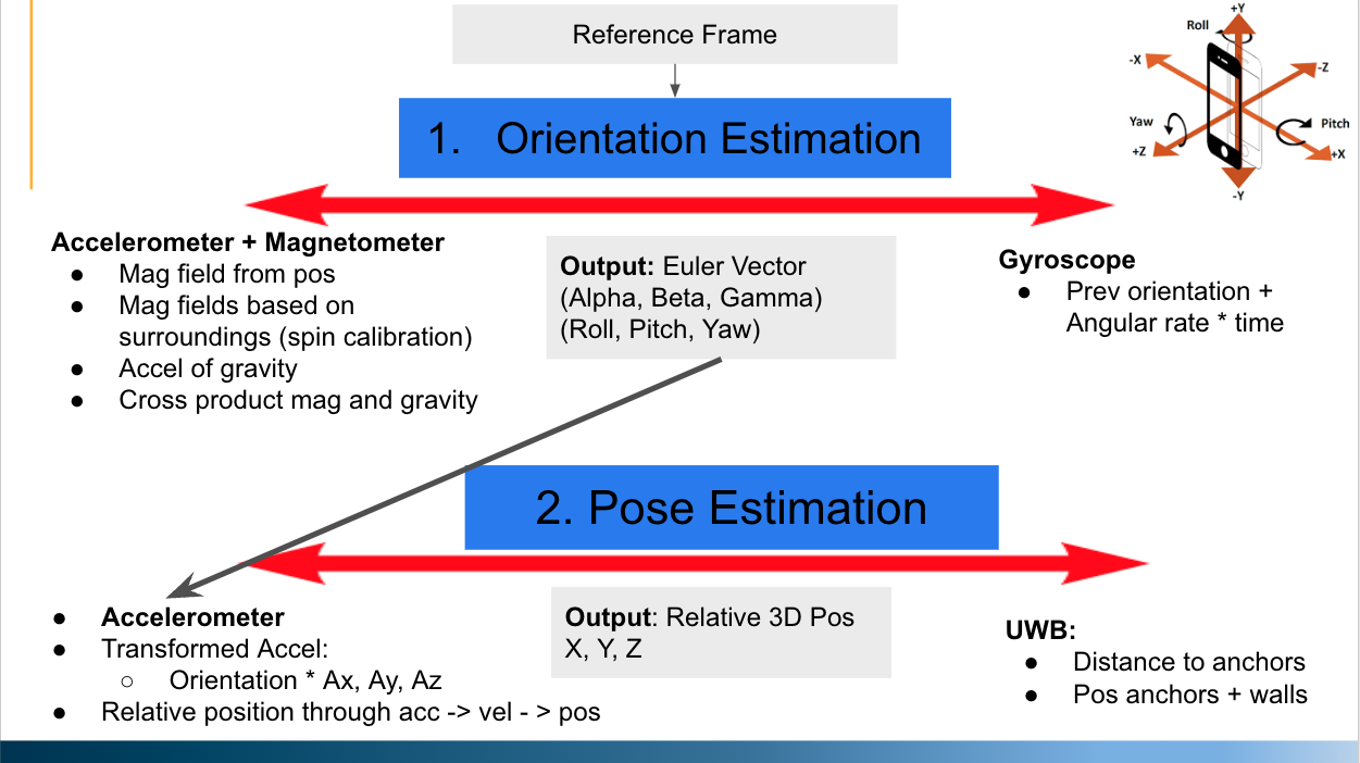
Figure 7: Methods to Detect Orientation and Pose Estimations
To achieve an accurate estimate of where a user is pointing a controller in free space, the two measurements that are needed are orientation (Alpha, Beta, Gamma) and pose (x, y, z).
To obtain an oreintation estimation the 9-DOF IMU was used. There are two ways that a 9-DOF IMU can detect orientation. The first method is by sensing where the magnetic fields point with the magnetometer and where gravity acceleration is pointing with the accelerometer. By taking the cross product of theses two vectors we can obtain relative orientation. The second method requires the original orienation and gyroscope data be known perfectly. If this assumption holds, the angular rotation multiplied by time will tell us the relative orientation of an object. The BN055 IMU and built in Arm Cortex M0 microprocessor provides custom software to fuse these two estimations together to make a fused orientation estimate which can be update at 100Hz.
To obtain a pose estimation, the goal of the project was to use the orientation estimation and fuse it with IMU and UWB measurements to get X, Y and Z cordinates. In theory there are two methods to get position with this approach. The first is if you know relative orientation of the controller to the room you are in, you can perform a tranformational rotation on the acceleration sensors to get relative x, y, and z positional accelerations.
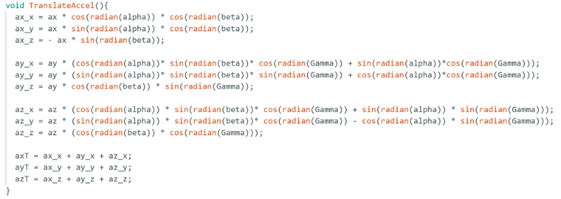
Figure 8: Arduino Rotation Matrix Calculation
By using the above translated accelerations, you can integrate acceleration to get velocity, and integrate velocity to get position. The biggest limiting factor with this approach is that the acceleromter is prone to drift. As position is a result of a double integrataion, positional error is accumulated over time. The second method that was initially used to estimate position was using one UWB anchor and tag, where the initial anchor position in the room was known. By having one tag in the room and getting a relative position movement measurment from the UWB, the anchor creates a sphere of possible positions that the tag could be in relation to the anchor. The idea was that over time if we combined positional changes seen by the accelerometer and distance observations from the UWB anchor, the possible locations where a user could be is reduced to one possible spot.
4. Evaluation and Results
Accelerometer Position Estimation Evaluation
To test the accuracies of accelerometer readings, a stationary IMU test was performed. This test involved placing the designed controller flat on a surface and averaging the first 30 samples of the stationary controller to get acceleration offsets. Once offsets were calculated, the sampling began where the controller would read the accelerometer readings minus the offsets. In a perfect world, the readings would show zero acceleration, however as expected there was drift errors. When the accelerations were integrated into velocity, and the velocities were integrated into position, the stationary test showed that soley relying on the acceleration data would have predicted 30m error in the x position, 600m error in the y position, and 40m error in the z direction.
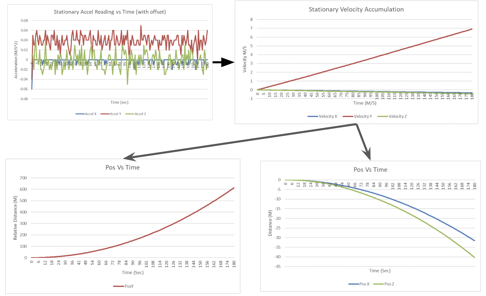
Figure 9: Stationary Test: Accelerometer Position Estimation Over 3 Minutes
IMU Orientation Estimation Evaluation
To test the accuracies of the Alpha, Beta, and Gamma values provided by the IMU fusion sensor, a stationary angle test was performed for each respective angle. For each test, the user would move the controller around for five seconds, then place the controller at the repective angle stationary for 5 seconds before an angle sample was taken. In total, 6 Alpha angles (0-360°), 9 Beta angles (-90, 90°), and 7 Gamma angles (-180, 180°) were tested, with ten samples tested per angle. The respective mean errors were calculated to be +/-37.27° for Alpha, +/-5.97° for Beta, and +/-4.26° for Gamma. One significant observation is that the angle that has the most significant error (Alpha) is also the angle that is likely the most impotant angle used when diferentiating objects in the room as it governs both the x and y pointing position for a line of sight when pointing in a room. Though the Gamma angle orientation is not used for determing where the line of sight is pointing for the controller, it is important when translations on the raw accelerometer values are made to get position estimations.
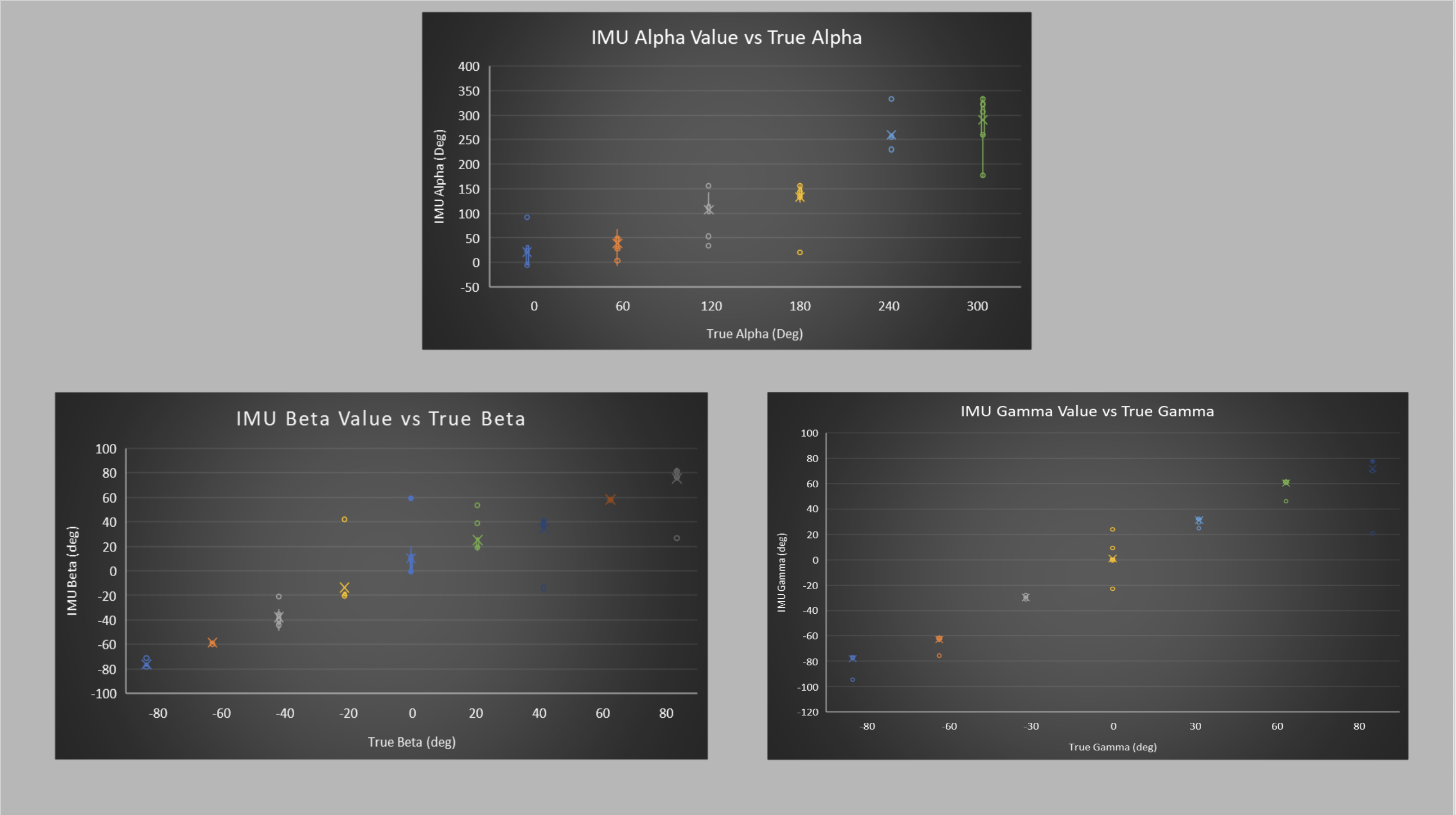
Figure 10: True Angle Versus Angle Estimation
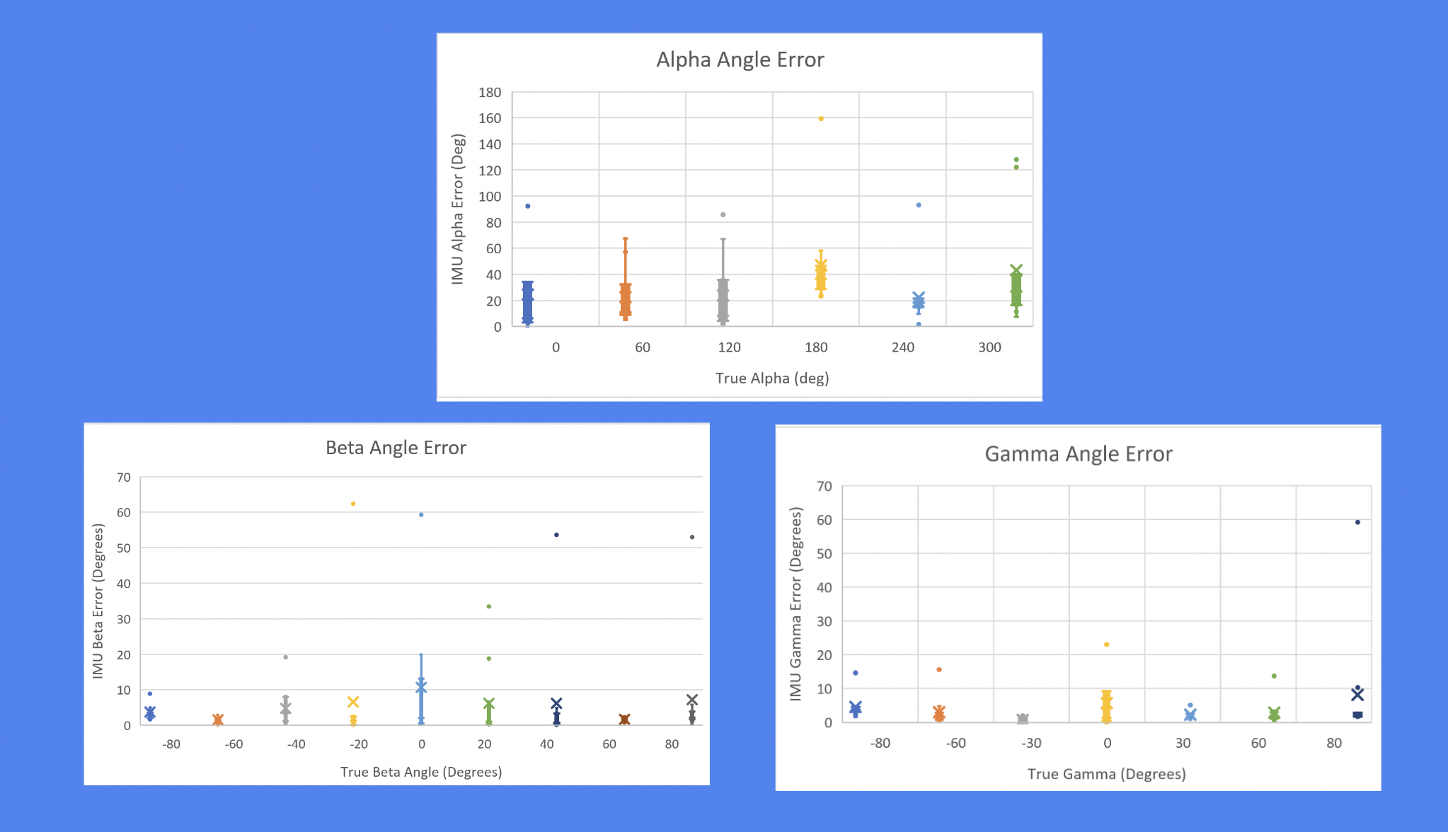
Figure 11: Average Angle Error for Alpha, Beta, Gamma Angles
Updated Postion approach
After discovering the significant noise that was present on the accelerometers, the next approach was to try and filter the accelerometer noise. A bandpass filter was added to the accelerometer to filter the data of interest. Thr high pass frequency was meant to filter out the drift and errors that were caused by inaccuracies from the transformations/orintation estimations and the low pass filter meant to filter out the noise in the accelerometers. The first step was to see if we could get indications of the direction that the controller was moving in a point in time, assuming that the object was at zero velocity. We were able to get general direction indiciations based on seeing accelerometer turning iniitially positive in one direction and the negative shortly after when the object deaccelerated. Anytime that this data was integrated however, the data would inconsistantly accumulate velocity in a way that was not indicative of the actual movement. Additionally, when the controller was tested not moving parrallel to one of the accelerometer axis, the transformations that were applied to get direction accumulated significant errors. This was due to incorrect angle transformations and since gravitational acceleration is so significant compare to normal human acceleration. This error in translations cause the gravitational acceleration to up in all directions and it rendered any non parrallel axis movement useless for giving information about directional movements. It was then decided that the nature of the accelerometer and its inaccuracies paired with the IMU sensor inaccuracies in orientation estimation made it not ccapable of being used for for position estimation.
The next direction taken to achieve accurate position estimation without using IMU data was moving from one UWB anchor to two. Though two tags are not normally enough to calculate position in 3d space, two tricks were applied to estimate position.
Trick One
After using the controller in a experimental setting, one observation made was that most of the time when the controller was being used, it would be held at the same or similar heights by the user with the height being based on the user. If we make the assumption that the user will be using the controller at similar Z plane heights, this siginificantly reduces the possibity of where the user could be located. Using some geometry techniques we can see that the intersection of a plane (z plane height) and a sphere reduces potential location of a user from a sphere to a circle.
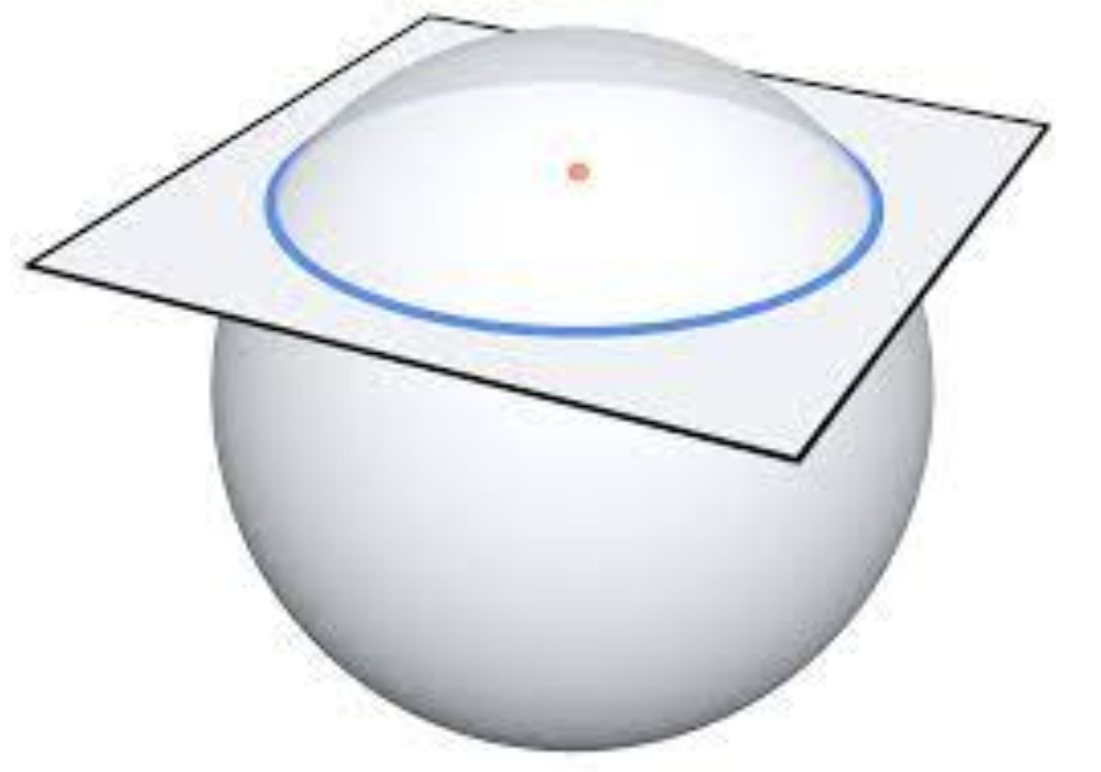
Figure 12: Trick 1, Assme user fixed height (Interection of plane and a sphere)
Trick Two
The next idea was to reduce the possible locations of the intersection of two circles from after applying trick 1. One initial idea was if we know the initial location, you can make assumtions about which of the two possible solutions in the circle intersects that the user would be in based on the fact that the user cannot just jump around between readings and so taking the closer solution to the previous solution. Though this may work, if the two intersections are close and the controller gets off then the estimations would quickly become very incorrect.
The final idea used was to strategically place the anchors. If we are assume we are in a rectangular room and place on tag in the corner and another along on of the neighboring walls, we cut off the solutions of the circle intersects of the room down to one possible location. This is possible because 3/4 of the circle is removed by the walls for the ancor placed in the corner and the 1/2 of the circle is removed by the walls for the anchor placed along the wall. This geometry reduction allows us to have only one point in the room where the user could be based on two tag readings.
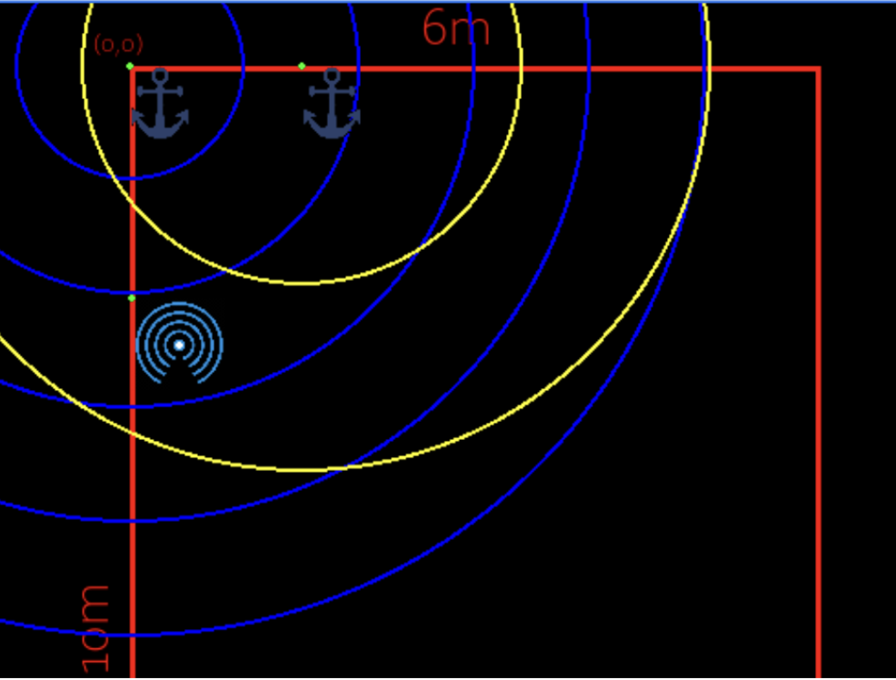
Figure 13: Trick 2, Strategic Anchor placement (Room circle intersects)
UWB Position Estimation Evaluation
In order to get accurate antennas readings for the UWB, each anchor antenna had to be tuned. Since the distance calculation includes both ToF and internal anchor delays, the anchor delay for each antenna had to be tested. To do this, the anchor antennas were placed at known distance locations and the relative time/distance calculations were made based off assumptions of various offsets. The delay was calculated by integrating the errors for each offset. After tuning the antennas, the UWB measurements were still noisy and inconsistantly not reading within the specified +/- 30cm accuracy of the devices. To reduce the noise, a 10 sample 10Hz moving average filter was applied and UWB measurements were then able to fall within the specified accuracies.
Line of Sight Object Detection
To detect where a user was intending to point, the position estimation and the orientation estimation were used. If all poisitions of the smart devices are known, then by knowing position and orientation of the controller we can imagine a line coming out of the top of the controller where the user is pointing. To determine which object the user is intending to select, we designed a virtual 1m sphere radius around the objects. If the pointing line crossed any where in that sphere of the objects it would be considered to be selected. If there was multiple object intersections, than to distinguish which item the user is pointing at, the closest distance from the line to the center point of the object was calculated, and which ever object was closer would be selected and could be controlled by the device.
GUI
To allow for visual represenation of the position, orentation, and object selection of the device, a python GUI was created. This GUI displays how the controller is estimated to be poistioned including the direction it is pointing (shown by the compass) and the tilt of the controller (shown by the tilt lines). It also renders the estimated user x and y positions in the room, the dimensions of the room, and displays the objects in the room (with configureable click placement). Finally, when an object is pointed at and the line of sight calculation detects selection,that object is rendered and can be controlled in the bottom right corner.
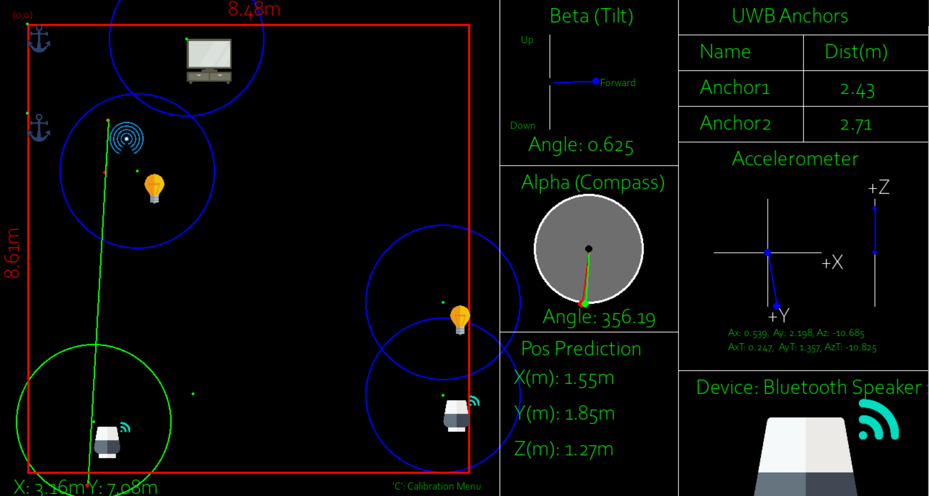
Figure 14: Image of GUI with user selecting/controlling bluetooth speaker
When an object is pointed at and the button on the controller is clicked, an illustration highlights the line of sight of the controller along with the device that was chosen. For proof of concept smart lights were added and would toggle upon button selection if chosen.
The following videos show the GUI inaction. Video 1 gives a demonstration of the IMU magnetometer sensing to show the response time and give a general idea of the accuracy. Video 2 shows a demonstration with two smart lights placed in a room. When moving around the room, each light could be selected indepedently to wirelessly toggle between on and off. Video 3 shows a similar demonstration however there are additional dummy smart devices placed in the room. These dummy smart devices allow us to show the ability of the system to distinguish between devices that are behind one another or very close to each other.
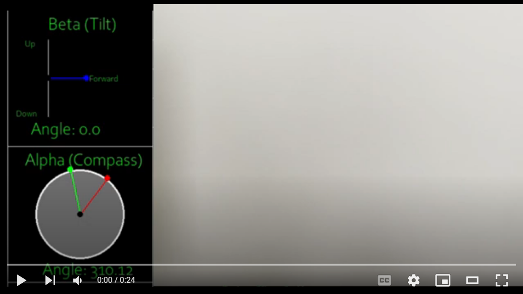
Video 1: Magnetometer Demo
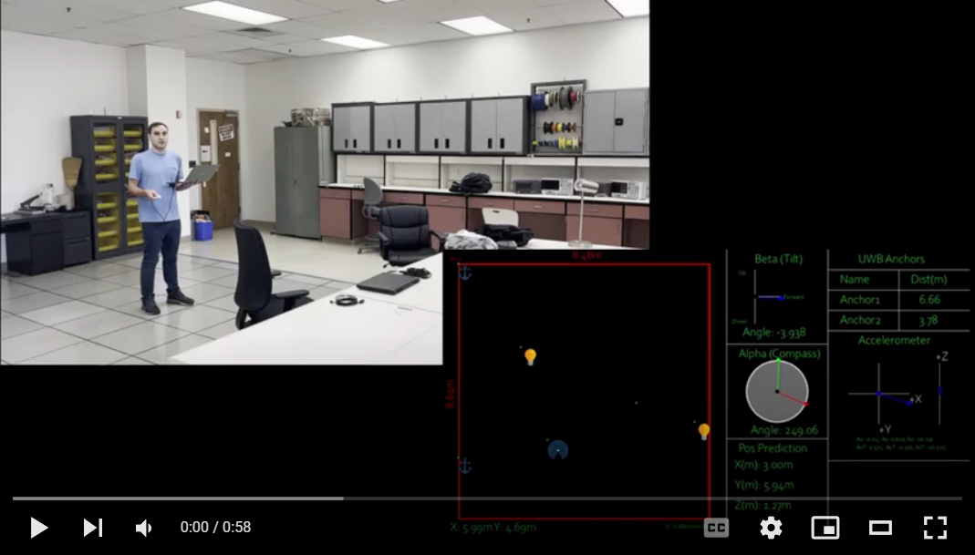
Video 2: Two Smart Device Demo
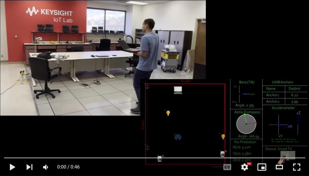
Video 3: 5 Smart Device Demo
5. Discussion and Conclusions
With the two UWB anchor approach, the system was successfully able to select and control multiple smart devices in the room. The video demostrations capture the capability of the system to perform both pose and orientation estimation in order to select and control multiple smart devices in close proximity. In order to achieve the original goal of creating a system that uses only one UWB anchor and the IMU sensor data more assumptions would need to made. The data shows that with no limit on the position of the IMU sensor on a human subject, there is far too much noise to draw any conclusions about the displacement at any given time. It is possible that some sophisticated denoising algorithm or deep learning approach would have allowed us to find some significance to the IMU data. However, problem of localizing with a freely moving IMU sensor by itself is a research topic of its own. Overall, the designed system was sucessfully able to to detect multiple smart devices as they were pointed to in a room, with accuracies that can be inferred based on distance to the objects and the angle and position inaccuracies listed above.
6. References
[1] Howarth, Josh. “80+ Amazing Iot Statistics (2023-2030).” Exploding Topics, Exploding Topics, 28 Nov. 2022, https://explodingtopics.com/blog/iot-stats.
[2] Ibrahim, Magdy, and Osama Moselhi. “IMU-Based Indoor Localization for Construction Applications.” Proceedings of the International Symposium on Automation and Robotics in Construction (IAARC), 2015, https://doi.org/10.22260/isarc2015/0059.
[3] Zwirello, Lukasz, et al. “UWB Localization System for Indoor Applications: Concept, Realization and Analysis.” Journal of Electrical and Computer Engineering, vol. 2012, 2012, pp. 1–11., https://doi.org/10.1155/2012/849638.